
软件工具
HBuilderX gem brew 会员管理系统 iopaint yaml Rider Auto GPT Airtest Stable Diffusion 飞书 Programmer AI Copilot X softwares for windows softwares for mac softwares for ios softwares for android Filezilla Cocoapods wireshark pyCharm Microsoft Edge vscode 短信关键字 Ubuntu 阿里云 视频下载 百度贴吧 百度云管家 爬虫 模拟器与手机 晨风QQ机器人 文件下载 按键精灵 抖音 微信 京东 云手机 yarn virtualbox vim truffle tor browser tomcat telegram sqlite3 spine shell shadowsocks scrapy scons rust repo pyenv preact pp助手 phpstorm pgAdmin pear pecl parity nvm npm nginx markdown magnet loadrunner laravel jekyll itunes iPhone heroku govendor google chrome gitlab github git eclipse docker cygwin composer cocos studio cmake carthage batch command apktool apachectl apache adobe photoshop adb aapt ZeroNet Xcode Windows WinHex WebStorm Visual Studio VMware TortoiseSVN ThinkSNS TexturePacker TeamViewer Subversion Sublime Text SourceTree SecureCRT SVN RTX QQ PostgreSQL OpenIM OpenGL Shader Builder OD Notepadplusplus Navicat for MySQL Mono MongoDB MinIO MinGW Microsoft Visual Studio Mac OS X Linux Laradock Kafka Jenkins Genymotion FontCreator ETCD CocosBuilder CentOS Bootstrap Beyond Compare Angular2 Android Studio 3ds Max 360 Visual Studio2010快捷键及设置 ChatGPT HRESULT 0x80004005 E_FAIL 美团开店宝 搜狗输入法 ohmyzsh meson golang mobile library gitea flutter多版本管理工具 - fvm _ WireGuard V2Ray RocketChat Fork Clash Advanced Installer Siliconflow ollama _ Google Colab DeepSeek ChatGPT局限性研究 AnythingLLM编程开发
Unity 团结 雷电模拟器闪退 微赞 golang在docker中运行 Open Source for Flutter Open Source for Android Android渲染 Unity UIWidgets Open Source for Unity Unity超链接 Unity spine Unity shader lua热重载 Bloom chrome extension Particle System Sprite Renderer Overdraw 字体描边 Unity热门插件 TronLink Bmfont TextMeshPro Behaviour Tree ThinkPHP ajax Hexagonal Grids python基础知识 python argparse和optparse eth eth layer2 ios点滴积累 exr UGUI优化 lua定义不允许定义变量的class 7za源码 打印堆栈 C C++点滴积累 android基础知识 xLua java基础知识 Unity DOTS Unity大规模角色渲染 Flutter metamask andriod源码编译 React Native git as a database android逆向 越狱 ios逆向开发 ipfs链编程 cocos2d-x3.x文字模糊 lua创建class v3quick 智能合约升级方案 gitlab服务器迁移 go调用C++ 区块链编程 cocos2dx lua项目转html5项目 SSL aar转jar Unity热更方案 Unity 升级 源码 反编译获取任何微信小程序源码 基础知识 cocos2dx ipv6支持 ClippingNode sprite的触摸事件 redis 加密算法 protobuf JAR creation failed. See details for additional information cocos2dx内存管理 SDK服务器 vpn服务器搭建 获取焦点 某些android系统下自动优化代码 异常处理 内存泄露分析 代码混淆 生成唯一id oauth2 IIS和tomcat共用80端口 enum MultiValueMap 易语言基础知识 MySQL eclipse的devices上不显示调试程序包名 搭建服务器下载文件 switch case的效率问题 获取版本号和版本名 cocos2d-js js语法 meta-data的获取 cocos2d-js安装 Paper2D rapidjson unreal源码赏析 NEON reload lua scripts go发邮件 smali语法 Spring lua枚举实现 PainTown编译 STL各容器操作 ios性能测试 UI Engines Game Engines Comparison CCActionInterval cocos bugs variadic templates singleton class POSIX g3log 不能在非主线程中使用OpenGL ES的UI函数 Menu get class name based on class #type 宏的含义 类模板的部分特化 各编译器对C++的支持度 Open Source Log Systems Comparison 百度语音识别SDK 锚点anchorPoint Unity插件 View Frustum Culling Matrix Layouts, DirectX and OpenGL DirectX基础知识 详解Cocos2d-X中宏CC_DLL android 国际化语言 locale缩写 android error solutions Unity调用webservice Unity调用C++的dll Unity Error Solutions 非组合BCD码VS组合BCD码 磁盘的磁道(track) use static Variables in static library ndk编译出错-Werror UNICODE字符集之 UTF-8、UTF-16 SpringBoard 无法启动应用程序 -4 Setting up a Code Repository on Google 透视投影变换 编译ogre_src_v1-7-4 windows 编译 ogre 1.9.0 ios undo 绘制次序 纹理寻址模式设置不当 显存带宽 bandwidth 分析碰撞检测库Opcode 《Fighting, Antiquity》遇见的各种问题 send TEXCOORD from DirectX9.0 to HLSL mul(inPos, matViewProjection) and mul(matViewProjection, inPos) A* Pathfinding X File Hierarchy Loading VS高亮HLSL关键字 Umbra 3:次世代的遮挡裁剪 Steering Behaviors For Autonomous Charac Rendering the Great Outdoors/Fast Occlusion Culling for Outdoor Environments Programming OpenGL ES with ios Perlin Noise OpenGL中freeglut的安装 OpenGL OpenGL ES hardware support OgreSDK_vc10_v1-7-4第一次编译程序运行crash Missing texture object named 'Texture0' in pixel shader 'Pixel Shader' in pass 'Pass 1' Loading .x files the easy way Load .obj model Get Texture Coordinates from DirectX in Vertex Shader Fx Composer Effect Framework DirectX 9.0中BeginPass和EndPass放置问题 DirectInput Coding in RenderMonkey Bézier curve Bullet Advanced Collision Detection Techniques 3D游戏引擎中的室外大场景渲染技术研究与实现 3D实时渲染中的BSP树和多边形剔除 fxc的使用及调试技巧 编译注意点 点滴积累 windows搭建android和cocos2dx环境 sprite::create("*.png")崩溃 Unknown EABI object attribute 44 CCUserDefault使用注意点 APP_STL := gnustl_static APP_CPPFLAGS := -frtti APP_CPPFLAGS += -fexceptions #pragma once与 #ifndef的区别 #ifdef _DEBUG 重载识别多重继承 返回值尽量返回const值 缺省实参编译时刻决定 编译器优化 纯虚析构函数必须定义 类继承中调用函数 类模板运用之实现委托类 类模板运用 类模板的友元 类成员函数声明为另外一个类的友元 析构函数出域就析构 指针的运用 成员函数模板和自动转换的选择 成员函数指针的运用 成员函数和非成员函数重载问题 在if里面请写入语句 使得打印出 hello world。 typedef作用 —— 定义机器无关的类型 static_cast注意点 static DWORD成员变量定义 operator<<重载 multimap容器不能用greater_equal case语句内定义变量 boost使用 本地函数定义是非法的 __attribute__ Type Conversion Override controls override and final OSI七层网络模型与TCP:IP四层网络模型 C:C++里面变量名的最大长度是多少? C++模板初始化 .h和.hpp区别 游戏崩溃查找dump crash堆栈信息 未签名的apk无法安装到手机上 延迟执行任务 平台接入 安装apk到手机中,elipse并非完全拷贝整个apk 多线程用多少个线程最合适 使用NDK编译so动态库 中国移动第三方接入 onNewIntent eclipse调试android程序 eclipse下android环境搭建 apk重启程序代码 apk 签名 ant 自动编译 android开发中遇到sqlite3 not found android制作九宫格图 android.database.CursorIndexOutOfBoundsException android 指定类 android ndk 开发之Application.mk android assets常见问题 android 4.0 NetworkOnMainThreadException ZXing竖屏解决(完美版) XP环境下java环境变量配置 Unable to execute dex/Multiple dex files define The nested fileset element is deprectated, use a nested path instead Re-installation failed due to different application signatures. ROM修改 NDK工具之 addr2line NDK和Eclipse的集成 MySQL相关 ListView无法在onCreate的时候getChildCount() JNI运用 Database Design/UUID vs Integer Auto-Increment Android点滴积累 Android查看内存 Android.mk文件详解 Android string Android NDK 官方下载地址 Adding ActionBar Items From Within Your Fragments Activity 生命周期 php环境搭建 Objective-C的方法原型和重载 c#反射机制 .NET入门 mac 下搭建lua环境 objective c点滴积累 OGRE点滴积累 Unity点滴积累 Unity NGUI lua基础知识 golang基础知识 typescript基础知识 solidity基础知识 php基础知识 nodejs基础知识 kotlin基础知识 javascript基础知识 html基础知识 C#基础知识 css基础知识 破解技术 assembly点滴积累 _ _ Unity 模型 Unity 优化 Unity Webview Unity Odin Unity Editor HybridCLR _ _ _ _ uniapp meteor kodi gopeed generative_agents _ VLC Media Player MPV MLN ChatDev _ _ Copay _ _ gradle _ _ _ _errors
MacOS 升级BigSur后无法使用git svn Unit php-fpm.service could not be found Uncaught ReferenceError process is not defined Uncaught ReferenceError Buffer is not defined thread.cc Throwing new exception length=433 index=1340 ArrayIndexOutOfBoundsException Provisioning profile doesn't include signing certificate indenting spaces must be used in groups of 2 Nokogiri install failures eth合约报错 xcode __nwlog_err_simulate_crash_libsystem pod生成工程后编译lib The SSL certificate is invalid php编译错误 not a valid ELF invalid resource directory name appcompat_v7 res crunch Invalid Code Signing Entitlements 该文件没有与之关联的程序来执行该操作 dyld Library not loaded rpathlibfmodL a2003- cant connect to MYSQL server on localhost android.view.WindowManager BadTokenException is your activity running android.view.WindowLeaked no suitable device found no device found for connection git push Server error goroutine 1 efrror RPC failed result=18 HTTP code 200 This version of the rendering library is more recent than your err 1005 Can't create table error 150 could not initialize proxy no Session could not execute query nested exception ArtifactDescriptorException Failed to read artifact descriptor is not a valid JNI reference INSTALL_FAILED_DEXOPT brut.androlib.AndrolibException ARSCDecoder.decode error 未在本地计算机上注册“Microsoft.Jet.OLEDB.4.0”提供程序 无法解析 __imp__printf 无法定位程序输入点sdl_strlcpy LNK1123: 转换到 COFF 期间失败: 文件无效或损坏 lwebsockets is not an object file Failed to git submodule update --recursive --init libpng error CgBI unhandled critical chunk symbol not found for architecture armv7 provider: 共享内存提供程序, error: 0 管道的另一端上无任何进程 and sa登陆失败 错误:18456 file is universal 3 slices but does not contain an armv7s slice error 126 无法解析的外部符号:error LNK2019 无法解析的外部符号 RegQueryValueEx、RegCloseKey、RegOpenKeyEx、RegSetValueEx... 无法解析外部符号 __imp__CoUninitialize@0、_TID_D3DRMFrameTransformMatrix 无法解析_c_dfDIMouse、_c_dfDIKeyboard、_DirectInput8Create@20、_c_dfDIJoystick2 无法解析 __imp__ExtractIconW@12、 __imp__ExtractIconW@12 无法打开文件"dxerr9.lib" 无法打开文件 d3dx9.lib 无法启动应用程序 1>------ 已启动生成: 项目: Init Direct3D, 配置: D 1>------ 已启动生成/项目/Font, 配置/Debug Win3 安装DirectXSDK时提示Error Code s1023 不允许使用不完整的类型 warning:DIRECTINPUT_VERSION undefined. Defaulting to version 0x0800 warning MSB8004: Output 目录未以斜杠结尾。此生成实例将添 warning C4996: 'strcpy': This function or variable may be unsafe. warning C4355: “this”: 用于基成员初始值设定项列表 warning C4290: 忽略 C++ 异常规范,但指示函数不是 __declspec(nothrow) warning C4003: “max”宏的实参不足 vs2010出现link2005 static_cast左右互搏
笔记本软件 Git Repositories Unity GUI 通讯协议 Open Source for nodejs Unity逆向工具 ps软件 NFT游戏 Open Source Audio 视频编辑软件 IM React Native Chat Library Messaging server backend go服务框架 浏览器 本地硬盘作服务器 自动按键 接码平台 数据清洗 go library for git go library for android ios React Native Apps Flutter Apps 加密算法 golang logging library python数据库框架 持续集成工具/Continuous integration(CI) 压缩存储 github guis git guis Gateway Server 图床工具 爬虫工具 lua远程调试器 去中心化数据库 去中心化云存储 noserver softwares php数据库框架 无服务器模式 服务器平台 宝塔 域名租用 php框架 文档管理工具 共识机制 库管理工具 区块链平台 量化交易 数字货币资讯软件 扩容方案 Web服务器 包管理工具 Web前端框架 交易所 Wallets DAPP Root工具 通用应用层协议 数据库 开发框架 数字货币 h5引擎 Open Source Cloud Disk 日志统计工具 博彩 团队协作工具 外包平台 ftp工具 remote control softwares log4j与slf4j 翻墙工具VPN scripting language low level graphics library Cygwin MinGW Build Tools 格斗引擎 shader tools UML Books 版本控制软件 Open Source Speech Recognition Physics Engines 远程控制软件 跨平台开发框架 自动测试工具 思维导图 序列化工具 工作流CI CD工具 局域网传输 uniapp开源框架 telegram server go library for server git in go app热更 _ PM常用工具 Optical Character Recognition(OCR) Open Source Video Player Open Source Shop Open Source Quantify Open Source Magnet Websites Open Source Chat点滴知识
日常 RPA 游戏工程设计细节 屏幕共享 AI Tool 工程规范 司法拍卖 第一性原理 数学 ecs 日语 科学锻炼记忆力 CPU缓存命中 OpenSea使用 apple store审核 博彩法律 BlockChain点滴积累 代扣支付平台 ios唯一标识 自制脱壳rom 自媒体 透明果实 飘三叶 斗牛 科幻 Fomo3D 区块链资源 googleplay支付 SSL证书安装 iPhone X全面屏适配 域名 SDK 生活 ipa重新打包 苹果过审 推广 王者荣耀 Pokemon GO 冒险与挖矿 Websites 规范 dnf地下城与勇士 实时对战手游 恐怖丛林肉搏 乱斗西游 专业常识 游戏开发书籍推荐 plist文件标识png图集的位置信息 mobile devices information 游戏设计书籍推荐 小说素材 正则表达式 Open Source Projects Daytoday Accumulation SEO 游戏同步 _数据结构与算法
背包问题 文件读取效率研究 随机选项和宽字符输出 过桥最短时间 输入一个正整数 设计一个程序 表达式求值 罗马数字与整数相互转换 编程求两个矩形的相交矩形 给定一个字串X 砝码称重 母函数问题 模拟实现乘法运算 某人有三个儿子 有一个长度为N的数字串 有5座不同颜色的房子 最长子串 最大子矩阵之和 在字符串S中寻找最 写一个程序 写一个函数 二维数组排序 一个线段随机分成三段能够构成三角形的概率 一个int数组,里面数据无任何限制,要求求出所有这样的数a[i], 其左边的数都小于等于它,右边的数都大于等于它。 能否只用一个额外数组和少量其它空间实现。 How many 0 appears Fabonacci数列定义为 Do remember 骆驼吃香蕉问题 错排原理 逻辑推理宴会握手 输入一个整数n 设计一个系统处理词语搭配问题 设计一个不能被继承的 设七位数是 编写代码把16进制表示的串转换为3进制表示的串 每个飞机只有一个油箱 概率问题 桌面上有24张光滑面扑克牌 根据上排给出十个数 有一个长度为998的数组 有一个复杂链表 有81个选手 有5个人比赛 有2.5亿个整数存放在一个文件中 有10个文件 无限容量的体育馆 数列L中有n个整数 把一个钝角三角形 循环队列 外星人打算将地球用来种蘑菇 在一天的24小时之中 判断另一字符串的所有字母是否在母串中都有 判断一个数是4的整数次幂 全部有火柴根组成 你有一个横6竖6的方格 九宫图解法 两个数组 不能使用库函数 下一个数是什么 一道小学数学题可以证明你是否可以玩股票 一个猜测游戏中 一个文件 一个教授逻辑学的教授 \[约瑟夫环\]n个数字 Longest Common Subsequence Fibonacci 12个高矮不同的人 100层楼 1000瓶药水 0-1背包 随机洗牌:哪种算法正确 求连续自然数平方和的公式 各种算法复杂度比较 教你如何迅速秒杀掉:99%的海量数据处理面试题 _ _undo
markdown usage todotodo
all todo标签
software 159
HBuilderX
gem
brew
会员管理系统
iopaint
yaml
Rider
Auto GPT
Airtest
Stable Diffusion
飞书
Programmer AI
Copilot X
softwares for windows
softwares for mac
softwares for ios
softwares for android
Filezilla
AI Tool
Cocoapods
wireshark
pyCharm
Microsoft Edge
vscode
短信关键字
Ubuntu
阿里云
视频下载
百度贴吧
百度云管家
爬虫
模拟器与手机
晨风QQ机器人
文件下载
按键精灵
抖音
微信
京东
云手机
yarn
virtualbox
vim
truffle
tor browser
tomcat
telegram
sqlite3
spine
shell
shadowsocks
scrapy
scons
rust
repo
pyenv
preact
pp助手
phpstorm
pgAdmin
pear pecl
parity
nvm
npm
nginx
markdown
magnet
loadrunner
laravel
jekyll
itunes
iPhone
heroku
govendor
google chrome
gitlab
github
git
eclipse
docker
cygwin
composer
cocos studio
cmake
carthage
batch command
apktool
apachectl
apache
adobe photoshop
adb
aapt
ZeroNet
Xcode
Windows
WinHex
WebStorm
Visual Studio
VMware
TortoiseSVN
ThinkSNS
TexturePacker
TeamViewer
Subversion
Sublime Text
SourceTree
SecureCRT
SVN
RTX
QQ
PostgreSQL
OpenIM
OpenGL Shader Builder
OD
Notepadplusplus
Navicat for MySQL
Mono
MinIO
MinGW
Microsoft Visual Studio
Mac OS X
Linux
Laradock
Jenkins
Genymotion
FontCreator
CocosBuilder
Beyond Compare
Angular2
Android Studio
3ds Max
360
ChatGPT
翻墙工具VPN
Cygwin MinGW
Build Tools
shader tools
UML Books
版本控制软件
美团开店宝
搜狗输入法
ohmyzsh
meson
golang mobile library
gitea
flutter多版本管理工具 - fvm
_
WireGuard
V2Ray
RocketChat
Fork
Clash
Advanced Installer
Siliconflow
ollama
_
Google Colab
DeepSeek
ChatGPT局限性研究
AnythingLLM
framework 14
android 64
雷电模拟器闪退
Open Source for Android
Android渲染
andriod源码编译
自制脱壳rom
aar转jar
JAR creation failed. See details for additional information
获取焦点
某些android系统下自动优化代码
异常处理
内存泄露分析
代码混淆
enum
MultiValueMap
eclipse的devices上不显示调试程序包名
获取版本号和版本名
js语法
meta-data的获取
smali语法
mobile devices information
android 国际化语言 locale缩写
android error solutions
游戏崩溃查找dump crash堆栈信息
未签名的apk无法安装到手机上
延迟执行任务
平台接入
安装apk到手机中,elipse并非完全拷贝整个apk
多线程用多少个线程最合适
使用NDK编译so动态库
中国移动第三方接入
onNewIntent
eclipse调试android程序
eclipse下android环境搭建
apk重启程序代码
apk 签名
ant 自动编译
android开发中遇到sqlite3 not found
android制作九宫格图
android.database.CursorIndexOutOfBoundsException
android 指定类
android ndk 开发之Application.mk
android assets常见问题
android 4.0 NetworkOnMainThreadException
ZXing竖屏解决(完美版)
XP环境下java环境变量配置
Unable to execute dex/Multiple dex files define
The nested fileset element is deprectated, use a nested path instead
Re-installation failed due to different application signatures.
ROM修改
NDK工具之 addr2line
NDK和Eclipse的集成
MySQL相关
ListView无法在onCreate的时候getChildCount()
JNI运用
Database Design/UUID vs Integer Auto-Increment
Android点滴积累
Android查看内存
Android.mk文件详解
Android string
Android NDK 官方下载地址
Adding ActionBar Items From Within Your Fragments
Activity 生命周期
gradle
_
back-end 11
cocos2dx 22
cocos2d-x3.x文字模糊
SSL
ClippingNode
sprite的触摸事件
cocos2dx内存管理
cocos2d-js
cocos2d-js安装
CCActionInterval
cocos bugs
不能在非主线程中使用OpenGL ES的UI函数
Menu
plist文件标识png图集的位置信息
锚点anchorPoint
详解Cocos2d-X中宏CC_DLL
编译注意点
点滴积累
windows搭建android和cocos2dx环境
sprite::create("*.png")崩溃
Unknown EABI object attribute 44
CCUserDefault使用注意点
APP_STL := gnustl_static APP_CPPFLAGS := -frtti APP_CPPFLAGS += -fexceptions
_
Unit php-fpm.service could not be found
Uncaught ReferenceError process is not defined
Uncaught ReferenceError Buffer is not defined
thread.cc Throwing new exception length=433 index=1340 ArrayIndexOutOfBoundsException
Provisioning profile doesn't include signing certificate
indenting spaces must be used in groups of 2
Nokogiri install failures
eth合约报错
xcode __nwlog_err_simulate_crash_libsystem
pod生成工程后编译lib
The SSL certificate is invalid
php编译错误
not a valid ELF
invalid resource directory name appcompat_v7 res crunch
Invalid Code Signing Entitlements
该文件没有与之关联的程序来执行该操作
dyld Library not loaded rpathlibfmodL
a2003- cant connect to MYSQL server on localhost
android.view.WindowManager BadTokenException is your activity running
android.view.WindowLeaked
no suitable device found no device found for connection
git push Server error goroutine 1
efrror RPC failed result=18 HTTP code 200
This version of the rendering library is more recent than your
err 1005 Can't create table error 150
could not initialize proxy no Session
could not execute query nested exception
ArtifactDescriptorException Failed to read artifact descriptor
is not a valid JNI reference
INSTALL_FAILED_DEXOPT
brut.androlib.AndrolibException ARSCDecoder.decode error
未在本地计算机上注册“Microsoft.Jet.OLEDB.4.0”提供程序
无法解析 __imp__printf
无法定位程序输入点sdl_strlcpy
LNK1123: 转换到 COFF 期间失败: 文件无效或损坏
lwebsockets is not an object file
Failed to git submodule update --recursive --init
libpng error CgBI unhandled critical chunk
symbol not found for architecture armv7
provider: 共享内存提供程序, error: 0 管道的另一端上无任何进程 and sa登陆失败 错误:18456
file is universal 3 slices but does not contain an armv7s slice
HRESULT 0x80004005 E_FAIL
error 126
无法解析的外部符号:error LNK2019
无法解析的外部符号 RegQueryValueEx、RegCloseKey、RegOpenKeyEx、RegSetValueEx...
无法解析外部符号 __imp__CoUninitialize@0、_TID_D3DRMFrameTransformMatrix
无法解析_c_dfDIMouse、_c_dfDIKeyboard、_DirectInput8Create@20、_c_dfDIJoystick2
无法解析 __imp__ExtractIconW@12、 __imp__ExtractIconW@12
无法打开文件"dxerr9.lib"
无法打开文件 d3dx9.lib
无法启动应用程序
1>------ 已启动生成: 项目: Init Direct3D, 配置: D
1>------ 已启动生成/项目/Font, 配置/Debug Win3
安装DirectXSDK时提示Error Code s1023
不允许使用不完整的类型
warning:DIRECTINPUT_VERSION undefined. Defaulting to version 0x0800
warning MSB8004: Output 目录未以斜杠结尾。此生成实例将添
warning C4996: 'strcpy': This function or variable may be unsafe.
warning C4355: “this”: 用于基成员初始值设定项列表
warning C4290: 忽略 C++ 异常规范,但指示函数不是 __declspec(nothrow)
warning C4003: “max”宏的实参不足
vs2010出现link2005
static_cast(pStr)
release版本下静态链接库无法解析外部符号
pragma warning(disable:4996)
gult32.dll
gorm查询sqlite3报错
general error c101008a_ Failed to save the updated manifest to the
ft2build.h file not found with include, use “quotes” instead
error X3025
error LNK2019 __imp__InitCommonControls@0
error LNK2001 无法解析的外部符号_mainCRTStartup
error C2443: 操作数大小冲突
crosses initialization
cmath(19): error C2061: 语法错误: 标识符“acosf”
ava.io.IOException Cannot run program jarsigner.exe
__imp__InitCommonControlsEx@4 __imp__EndDialog
__gmsl:512:*** non-numeric second argument to `wordlist' function: ''.
_ITERATOR_DEBUG_LEVEL”的不匹配项问题
_ITERATOR_DEBUG_LEVEL
XCode: duplicate symbol error when using global variable - Stack Overflow
Application does not specify an API level requirement!
VS2010 fatal error C1902: 程序数据库管理器不匹配;请检查安装
S1023 error on installing DirectX SDK
LNK4006 symbol already defined in object; second definition ignored
LNK2001 : unresolved externals
IDirectSound8无法使用
Failure Reason Message from debugger Terminated due to memory issue
DirectX Preview window: WARNING: Pixel shader 'Pixel Shader' cannot be created on hardware rendering
COMMON ERROR - python
无法解析的外部符号 __imp__ExtractIconW@12
_
lua 9
unity3d 32
Unity 团结
Unity UIWidgets
Open Source for Unity
Unity超链接
Unity spine
Unity shader
Bloom
Particle System
Sprite Renderer
Overdraw
字体描边
Unity热门插件
Bmfont
TextMeshPro
UGUI优化
Unity DOTS
Unity大规模角色渲染
Unity热更方案
Unity 升级
Unity插件
Unity调用webservice
Unity调用C++的dll
Unity Error Solutions
Unity点滴积累
Unity NGUI
_
Unity 模型
Unity 优化
Unity Webview
Unity Odin
Unity Editor
HybridCLR
algorithm 86
Behaviour Tree
Hexagonal Grids
背包问题
域名
ipa重新打包
苹果过审
cocos2dx ipv6支持
redis
加密算法
protobuf
生成唯一id
文件读取效率研究
随机选项和宽字符输出
过桥最短时间
输入一个正整数
设计一个程序
表达式求值
罗马数字与整数相互转换
编程求两个矩形的相交矩形
给定一个字串X
砝码称重
母函数问题
模拟实现乘法运算
某人有三个儿子
有一个长度为N的数字串
有5座不同颜色的房子
最长子串
最大子矩阵之和
在字符串S中寻找最
写一个程序
写一个函数
二维数组排序
一个线段随机分成三段能够构成三角形的概率
一个int数组,里面数据无任何限制,要求求出所有这样的数a[i], 其左边的数都小于等于它,右边的数都大于等于它。 能否只用一个额外数组和少量其它空间实现。
How many 0 appears
Fabonacci数列定义为
Do remember
骆驼吃香蕉问题
错排原理
逻辑推理宴会握手
输入一个整数n
设计一个系统处理词语搭配问题
设计一个不能被继承的
设七位数是
编写代码把16进制表示的串转换为3进制表示的串
每个飞机只有一个油箱
概率问题
桌面上有24张光滑面扑克牌
根据上排给出十个数
有一个长度为998的数组
有一个复杂链表
有81个选手
有5个人比赛
有2.5亿个整数存放在一个文件中
有10个文件
无限容量的体育馆
数列L中有n个整数
把一个钝角三角形
循环队列
外星人打算将地球用来种蘑菇
在一天的24小时之中
判断另一字符串的所有字母是否在母串中都有
判断一个数是4的整数次幂
全部有火柴根组成
你有一个横6竖6的方格
九宫图解法
两个数组
不能使用库函数
下一个数是什么
一道小学数学题可以证明你是否可以玩股票
一个猜测游戏中
一个文件
一个教授逻辑学的教授
\[约瑟夫环\]n个数字
Longest Common Subsequence
Fibonacci
12个高矮不同的人
100层楼
1000瓶药水
0-1背包
正则表达式
随机洗牌:哪种算法正确
求连续自然数平方和的公式
各种算法复杂度比较
教你如何迅速秒杀掉:99%的海量数据处理面试题
_
game-engine 57
exr
xLua
Paper2D
rapidjson
unreal源码赏析
NEON
PainTown编译
scripting language
low level graphics library
格斗引擎
ios性能测试
UI Engines
Game Engines Comparison
g3log
Open Source Log Systems Comparison
View Frustum Culling
Matrix Layouts, DirectX and OpenGL
DirectX基础知识
Physics Engines
透视投影变换
编译ogre_src_v1-7-4 windows
编译 ogre 1.9.0 ios undo
绘制次序
纹理寻址模式设置不当
显存带宽 bandwidth
分析碰撞检测库Opcode
《Fighting, Antiquity》遇见的各种问题
send TEXCOORD from DirectX9.0 to HLSL
mul(inPos, matViewProjection) and mul(matViewProjection, inPos)
A* Pathfinding
X File Hierarchy Loading
VS高亮HLSL关键字
Umbra 3:次世代的遮挡裁剪
Steering Behaviors For Autonomous Charac
Rendering the Great Outdoors/Fast Occlusion Culling for Outdoor Environments
Programming OpenGL ES with ios
Perlin Noise
OpenGL中freeglut的安装
OpenGL
OpenGL ES hardware support
OgreSDK_vc10_v1-7-4第一次编译程序运行crash
Missing texture object named 'Texture0' in pixel shader 'Pixel Shader' in pass 'Pass 1'
Loading .x files the easy way
Load .obj model
Get Texture Coordinates from DirectX in Vertex Shader
Fx Composer
Effect Framework
DirectX 9.0中BeginPass和EndPass放置问题
DirectInput
Coding in RenderMonkey
Bézier curve
Bullet
Advanced Collision Detection Techniques
3D游戏引擎中的室外大场景渲染技术研究与实现
3D实时渲染中的BSP树和多边形剔除
fxc的使用及调试技巧
OGRE点滴积累
java 59
java基础知识
andriod源码编译
aar转jar
JAR creation failed. See details for additional information
获取焦点
某些android系统下自动优化代码
异常处理
内存泄露分析
代码混淆
enum
MultiValueMap
eclipse的devices上不显示调试程序包名
获取版本号和版本名
js语法
meta-data的获取
smali语法
mobile devices information
android 国际化语言 locale缩写
android error solutions
游戏崩溃查找dump crash堆栈信息
未签名的apk无法安装到手机上
延迟执行任务
平台接入
安装apk到手机中,elipse并非完全拷贝整个apk
多线程用多少个线程最合适
使用NDK编译so动态库
中国移动第三方接入
onNewIntent
eclipse调试android程序
eclipse下android环境搭建
apk重启程序代码
apk 签名
ant 自动编译
android开发中遇到sqlite3 not found
android制作九宫格图
android.database.CursorIndexOutOfBoundsException
android 指定类
android ndk 开发之Application.mk
android assets常见问题
android 4.0 NetworkOnMainThreadException
ZXing竖屏解决(完美版)
XP环境下java环境变量配置
Unable to execute dex/Multiple dex files define
The nested fileset element is deprectated, use a nested path instead
Re-installation failed due to different application signatures.
ROM修改
NDK工具之 addr2line
NDK和Eclipse的集成
MySQL相关
ListView无法在onCreate的时候getChildCount()
JNI运用
Database Design/UUID vs Integer Auto-Increment
Android点滴积累
Android查看内存
Android.mk文件详解
Android string
Android NDK 官方下载地址
Adding ActionBar Items From Within Your Fragments
Activity 生命周期
c++ 43
打印堆栈
switch case的效率问题
STL各容器操作
variadic templates
singleton class
POSIX
get class name based on class
#type 宏的含义
类模板的部分特化
各编译器对C++的支持度
#pragma once与 #ifndef的区别
#ifdef _DEBUG
重载识别多重继承
返回值尽量返回const值
缺省实参编译时刻决定
编译器优化
纯虚析构函数必须定义
类继承中调用函数
类模板运用之实现委托类
类模板运用
类模板的友元
类成员函数声明为另外一个类的友元
析构函数出域就析构
指针的运用
成员函数模板和自动转换的选择
成员函数指针的运用
成员函数和非成员函数重载问题
在if里面请写入语句 使得打印出 hello world。
typedef作用 —— 定义机器无关的类型
static_cast注意点
static DWORD成员变量定义
operator<<重载
multimap容器不能用greater_equal
case语句内定义变量
boost使用
本地函数定义是非法的
__attribute__
Type Conversion
Override controls override and final
OSI七层网络模型与TCP:IP四层网络模型
C:C++里面变量名的最大长度是多少?
C++模板初始化
.h和.hpp区别
mac 7
ios 12
game-design 15
eth 2
Load .obj model
2014年09月04日- Introduction
- .obj File Format
- Right Hand Vs. Left Hand Coordinate Systems
Introduction
In this lesson, we will learn how to load a 3d model from an obj file. .obj files are ascii based files, so they are easy to read. Along with .obj files is the .mtl file, which is the material library. We will also learn to load the materials for the model using the .mtl file. .obj files are large and contain no animation, so you will usually want to use a different model format for video games. However, the .obj format is a great file to start with when learning how to load models! This is a longer lesson, so i will go through in sections, instead of line by line like i usually like to do. Let’s get to it!
.obj File Format
.obj files have been around for a long time. They are one of the oldest 3d model formats out there, but still widely used. .obj files do not contain header information like other file formats. Headers are the beginning of a file which will give you information about it. For example a header in a 3d model file might tell you how many vertices, texture coordinates, normals, materials, subsets, and faces there are in the file. Since .obj files do not contain this information, we can do one of two things. The first thing we could do is read the file twice. The first read would gather information like how many vertices, faces, normals, etc. there are, so we can initialize arrays for each. The second read would get the actual model information, like vertex positions, and store them in the initialized arrays. This is the inneficient way of how it used to be done before we had something called “vectors”. The second way we can load an obj file, and the way we will do it, is use vectors. A vector is a dynamic array (which you should already know), where instead of initializing it with a set size, we can “push_back” elements to increase the size as we need. Another cool thing about vectors is they clean themselves, so we do not need to “delete” them like we do standard arrays. Using this method, we only need to read the file once, and store the models information in the vectors as we go. Each piece of information in an obj file is (supposed to be…) put onto it’s own line, where a string of one or more characters (eg. “v”) explains what the rest of the information on that line is used for, and “\n” is the terminating character of each line. Here is an example of a sample .obj file taken from the one this lesson uses:
# 3ds Max Wavefront OBJ Exporter v0.97b - (c)2007 guruware
# File Created: 26.07.2011 13:47:43

mtllib spaceCompound.mtl

#
# object Window
#

v  -8.6007 1.3993 10.0000
v  -8.6007 8.6007 10.0000
...
# 4 vertices

vn 0.0000 0.0000 -1.0000
# 1 vertex normals

vt 0.0000 0.0000 0.0000
vt 0.0000 1.0000 0.0000
...
# 4 texture coords

g Window
usemtl Window
f 1/1/1 2/2/1 3/3/1
f 3/3/1 4/4/1 1/1/1
# 2 faces   ## "#" - Comments
# 3ds Max Wavefront OBJ Exporter v0.97b - (c)2007 guruware   Comments start the line with "#". Whenever you read a "#", you can skip that line. ## "mtllib" - Material Library File   mtllib spaceCompound.mtl   mtllib is the start of a line which contains a material library filename. A material library is a separate file that goes with .obj files, which define the materials for each group. .obj files don't always contain a library file, but they usually do. Not only that but once in a while they may contain multiple library files. It shouldn't be too hard to modify the code to take this into consideration when reading an obj file. ## "v" - Vertex Positions   v  -8.6007 1.3993 10.0000   Lines containing a vertex position are started with "v". Vertex positions follow the (x, y, z) format, where each number is separated by a single space. ## "vn" - Normals   vn 0.0000 0.0000 -1.0000   Lines containing a vertex normal are started by "vn". Vertex normals follow the (x, y, z) format, where each number is also separated by a single space. They are used to specify which direction a triangle is facing, which can be used to impliment lighting. To get smooth lighting across a surface you will usually want to do something called "normal averaging", which is finding the normal for each face sharing a single vertex, then average them together to get that vertices normal. In this lesson we will not need to load vertex normals from the file, as we will learn how to create our own vertex normals. However, for completion, we do load the normals in from the file, but do not use them. ## "vt" - Texture Coordinates   vt 0.0000 1.0000 0.0000   Lines containing texture coordinate data are started with "vt". Texture coordinates are used to correctly map an image to a triangle or set of triangles. They follow the (u, v, w) format, where each number is separated by a single space. Usually you will only need a "u" and "v" coordinate for mapping 2d images, but sometimes you might use a cubic texture (3d texture) to map round objects such as spheres, where you will need the "w" coordinate. ## "o" - Objects   o spaceCompound   The obj file for this lesson does not specify "o". Objects are a group of groups. An example is a town, where you might have a couple houses, which would each be considered objects, and each house contains groups, like windows, doors, walls, roof, etc. ## "g" - Groups (Subsets)   g Window   Groups are a set of faces which all use the same attributes, such as the same material. In this example, we have a group for the window, each of the rooms, and each of the doorways between rooms. We will call groups "subsets" in this lesson. ## "usemtl" - Group Materials   usemtl Window   Like what was said a moment ago, each group contains a Material, and lines specifying which material to use are started with "usemtl". The materials are found in the material library (.mtl) file usually accompanying an obj file. In this lesson, we have two materials, a transparent material for the window, and a textured material for the walls. ## "s" - Smoothing Groups   s 1   ...   s 2   ...   Smooth shading can also be turned off   s off   Smooth shading can be used to for smoothing across groups. This can create a nice round looking surface. We will not get into this in this lesson, so we will just skip lines with "s". ## "f" - Faces A face containing a position, texture coordinate and normal
f 1/1/1 2/2/1 3/3/1 A face containing a position, and a normal
f 1//1 2//1 3//1
A face containing a position, and a texture coordinatef 1/1 2/1 3/1
A face containing only a positionf 1 2 3
Lines defining a face are started with “f”. Faces are a set of three or more vertices, where each vertex follows the format “Position/Texture Coordinate/Normal”. Each vertex is separated by a space. Each vertex defined in a face can contain a position and/or a texture coordinate, and/or a normal, where each number is separated by a “/”. If a vertex contains only a position, there is no “/”, if it contains a position and a texture coordinate, there is only one “/”, which is between the two number. If the vertex contains a position, texture coordinate and a normal, there is a “/” between all three numbers. And last, if it contains only a position and a normal, there is a “//”, or TWO “/” between the numbers. The numbers represent an index value STARTING WITH “1” from the beginning of the file. I stress the “starting with 1” because C++ arrays start with “0”, so you MUST subtract one from these numbers before storing them. I’m going to try to make this a little more clear. Consider the line “f 1 2 3”. This face contains only a position for each vertex. So at the beginning of the file, the first vertex position was read, “v -8.6007 1.3993 10.0000”. The “1” in the face “1 2 3” represents this vertex position. However, in C++ (in our code) when we stored this vertex position, we stored it in the [0] element of the vector. So when we store this face, we need to actually store it like this “0 1 2” instead of “1 2 3”. And when there is multiple groups and objects, the numbers are still based on the collective index value for each defenition starting from the beginning of the file. One more thing about faces, is they are not always stored as triangles in an obj file. Sometimes they are stored as squares or other shapes containing more edges. Here is an examplef 1 2 3 4 5
DirectX can only work with triangles. So we must take this into consideration when getting these faces. To fix this problem, we will turn each polygon with more vertices than three into triangles. We will do this by taking the first three vertices in a face and making a triangle of it. Each vertex defined after is a new triangle. We can make a new triangle by taking the very first vertex defined in the face, and use it as the first vertex for every other triangle in the current face. Then take the last vertex of the triangle before the current one, and use that as the second vertex in the current triangle. For example, the polygon above is defined by “1 2 3 4 5”. We will need to turn this into three triangles, because the first three make up the first triangle, and the two after the first three are two new triangles. So the three triangles will look like this:tri1 = “1 2 3” tri2 = “1 3 4” tri3 = “1 4 5”
I want to mention one more thing about faces in obj models. Some programs such as lightwave are able to make shapes that are concave… An example of a concave shape is pacman, or a star. The problem with this is that when we create triangles from the vertices of this shape, some of the triangles will “overlap” other triangles. Have a look below.
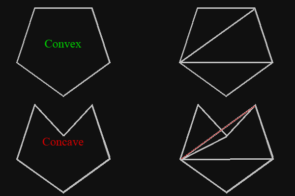
You can fix this problem by calculating the angle between edges to find where it is concave, and retriangulate the face depending on the concavities, but we will not do that in this lesson.
.mtl File Format
The mtl file is the material library for the object file. This file will contain the surface properties of each group. Not all obj models include a material library file, but we will assume our’s do. As was mentioned above, this lesson’s model uses two materials, one for the window, and the other for the walls. Loading the model is not the ONLY new thing in this lesson. We have now created a “SurfaceMaterial” structure, which will hold the various surface properties of each subset, such as diffuse color, transparency, and textures. We will cover this structure soon enough, but for now lets look at the mtl file’s contents. This is the mtl file that we will be using for this lesson.
# 3ds Max Wavefront OBJ Exporter v0.97b - (c)2007 guruware
# File Created: 26.07.2011 13:47:43

newmtl Window
    Ns 32.0000
    Ni 1.5000
    d 0.8000
    Tr 0.2000
    Tf 1.0000 1.0000 1.0000
    illum 2
    Ka 0.0000 0.0000 0.0100
    Kd 0.0000 0.0000 0.0100
    Ks 0.3500 0.3500 0.3500
    Ke 0.0000 0.0000 0.0000

newmtl MetalPanels
    Ns 10.0000
    d 1.0000
    Tr 0.0000
    Tf 1.0000 1.0000 1.0000
    illum 2
    Ka 0.5882 0.5882 0.5882
    Kd 0.5882 0.5882 0.5882
    Ks 0.0000 0.0000 0.0000
    Ke 0.0000 0.0000 0.0000
    map_Ka metalpanel.jpg
    map_Kd metalpanel.jpg
    map_bump metalpanelnormals.jpg ## "#" - Comments
# 3ds Max Wavefront OBJ Exporter v0.97b - (c)2007 guruware   mtl files also contain comments, and again they start the line with "#". We can skip lines starting with "#". ## "newmtl" - New Material
newmtl Window   A new material is started with "newmtl". The word after "newmtl" is the name of the material. Everything after "newmtl" is that materials defenition, until another "newmtl" is reached, or the end of file (eof) is reached. ## "Ns" - Specular Power
Ns 10.0000   A line starting with "Ns" is the specular power of the surface. The value can range from "0" to "1000", where 1000 is the highest power of specular, or most reflective of light. ## "Ni" - Optical Density
Ni 1.5000   A line starting with "Ni" is the optical density of the surface. The value can range from "0" to "10", where 10 is the most dense. Optical density is used to "bend light" for transparent surfaces. ## "d" - Transparency(it's 不透明度)
d 0.8000   A line starting with "d" is the transparency of the surface. The value can range from "0" to "1", where 0 is completely transparent, or invisible. ## "Tr" - Transparency
Tr 0.2000   A line starting with "Tr" is also the transparency of the surface. Some obj models use either "d", "Tr", or both to define the transparency of a material. The value can range from "0" to "1", but this time 1 is completely transparent or invisible. ## "Tf" - Transmission Filter
Tf 1.0000 1.0000 1.0000   This one has to do with light passing through a transparent surface. The light passing through a transparent surface is filtered by this attribute. ## "illum" - Illumination Model
illum 2   The illumination model is a value between 0 and 10. Each number is a different equation which impliments lighting and shading for a surface. We won't worry about these here. ## "Ka" - Ambient Color
Ka 0.0000 0.0000 0.0100   This is the color of the surface when no light is hitting it. Usually this is the same as the diffuse color of the surface, so in this lesson, we will load this value into the diffuse color of our material if there is no diffuse color defined. ## "Kd" - Diffuse Color
Kd 0.0000 0.0000 0.0100   This is the actual color of our material. If there is no diffuse texture defined for the material, we will use this color to color the surface using this material. ## "Ks" - Specular Color
Ks 0.3500 0.3500 0.3500   We will not use specular color in this lesson, but we will in an upcoming lesson. This is the color of the specular light which is reflected off of shiny surfaces. ## "Ke" - Emissive Color
Ke 0.0000 0.0000 0.0000   Emissive color is the color of a surface when it "lights up". For example a lightbulb. When a lightbulb is off, it might look dark grey, but when it is turned on, it turnes bright white. Emissive lighting is used to "light up" the surface which is sending light out. In video games, a lightbulb may not actually light itself up when sending out light, so we need to give it emissive light. This is not used in this lesson, but would be easy to impliment if needed. ## "map_Ka" - Ambient Color Map
map_Ka metalpanel.jpg   This is the texture used for the ambient color of a surface. This is almost always the same as the diffuse texture。 ## "map_Kd" - Diffuse Color Map
map_Kd metalpanel.jpg   This is the texture or image used to do the actual coloring of the surface. ## "map_Ks" - Specular Color Map
map_Ks metalpanel.jpg   This is the texture or image used to say how "shiny" the different parts of a surface are. ## "map_bump" or "bump" - Bump Map
map_bump metalpanel.jpg
bump metalpanel.jpg   Bump maps are used to give the surface actual texture, where some parts of a surface may appear to be a little deeper, while others appear to be sticking out. We will be using normal maps in place of bump maps in a later lesson. # Right Hand Vs. Left Hand Coordinate Systems Directx uses a "Left Hand Coordinate System". What this means is that the positive direction of the z-axis is facing away from the camera, while the right hand coordinate system's positive z-axis is facing towards the camera. positive y is facing up, positive x is facing right. A lot of modeling programs such as maya and 3ds max use a right handed coordinate system. Since directx uses a left had coordinate system, we will need to convert these models into a left hand coordinate system. To convert from right hand to left hand, we must do a couple things. First is invert the z-axis of the vertice's positions by multiplying it with -1.0f. We will also need to invert the v-axis of the texture coordinats by subtracting it from 1.0f. Finally we will need to convert the z-axis of the vertex normals by multiplying it by -1.0f. I have put a boolean variable in the parameters of the load model function, where if it is set to true, we will do the conversion, and if it is set to false we will not do the conversion. # Transparent Subsets We have taken transparency into consideration when loading models in this lesson. Remember from the blending lesson, that the blending technique works by "blending" whats already on the render target with the transparent object. Because of this, we need to make sure that the transparent subsets are the last thing drawn. We have also talked about multiple transparent objects in the blending lesson, but I will quickly go over the solution here. We will not impliment this technique, but a more advanced technique of the drawing order of transparent objects would be to find their distance from the camera, and draw them from furthest to nearest. You may run into this problem which is why I wanted to mention it. # The Removal of the Mesh Interface (eg. ID3DX10Mesh) Direct3D 11 has removed the mesh interface. Because of this, we now need to handle all the 3d model stuff by hand, such as the vertex and index buffers, subset counts, mesh intersection (which was damn usefull for picking a 3d object with the mouse). Anyway, its not a huge problem, but instead of loading the 3d model from the file directly to a mesh object, we will now need to store the vertices and index list into buffers, and keep track of subsets and materials. I wanted to mention this to you before we begin! If you have read other lessons on this site, you have no doubt noticed they don't use classes. This is because I try to make the lessons's code easy to read straight through (classes can make reading code more time consuming because you have to jump around the code to see whats happening). Classes make code MUCH more efficient, and you will most definitely want to use classes when making a game. So in the bottom of this lesson I have included an exercise to make a mesh class including methods to load the model from a file and to draw the models subsets, and members to store the models information to replace the removed mesh interface.